

What Architects Need to Know About Raised Access Floors in Data Centres
A data hall’s finished floor level can determine the length of an access ramp, the clear height above server racks and the space available for services below. Once the building section and room layout are fixed, changing any of these can become very complicated.
A raised access floor can provide accessible routes for services and, in some designs, distribute conditioned air. For architects, the task is to establish what the floor must do, then coordinate the complete system with the structure, equipment and building services. The following decisions are worth resolving before the design is locked in.
Decide What the Floor Needs to Do
Start with the data centre’s infrastructure strategy. Will power and data run below the floor? Will the void form part of the air distribution system? What needs to remain accessible for maintenance or future changes?
A raised floor is not required in every data centre. Some projects use a structural slab with overhead services and a different cooling arrangement. The choice should follow the equipment and services design. For a broader introduction to the system and its benefits, see our guide to raised access flooring in data centres.

Set the Finished Floor Level in Section
The finished floor height must allow for the panel and understructure as well as the clear space needed for services or airflow. A specified floor build-up is not the same as usable plenum depth. Ask the mechanical and electrical teams what must pass beneath the floor, how it will be accessed and whether the void will be pressurised.
Then test that level against the rest of the building: adjacent rooms, door thresholds, accessible routes, equipment delivery paths and the clear height needed above racks for cable trays, containment or other overhead systems. A depressed structural slab may help achieve level transitions in a new build, but it must be coordinated early with the structural design. An existing building may call for a different solution.
Show the structural slab, finished floor level, underfloor clearances and overhead zone on the same sections. This exposes competing space requirements before they become site issues.
Specify Loads Across the Complete Floor System
A cabinet’s total weight is only the starting point. The same weight can affect the floor differently depending on where its feet or castors land and how equipment is moved into the room. The specification should account for:
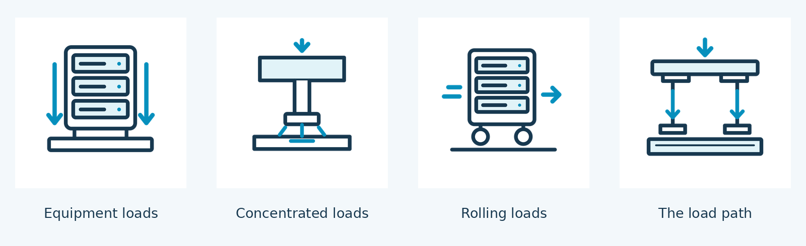
Equipment loads: fully populated cabinet weights, footprints and likely future configurations.
Concentrated loads: the number, size and position of levelling feet or castors, including their location relative to panel edges and supports.
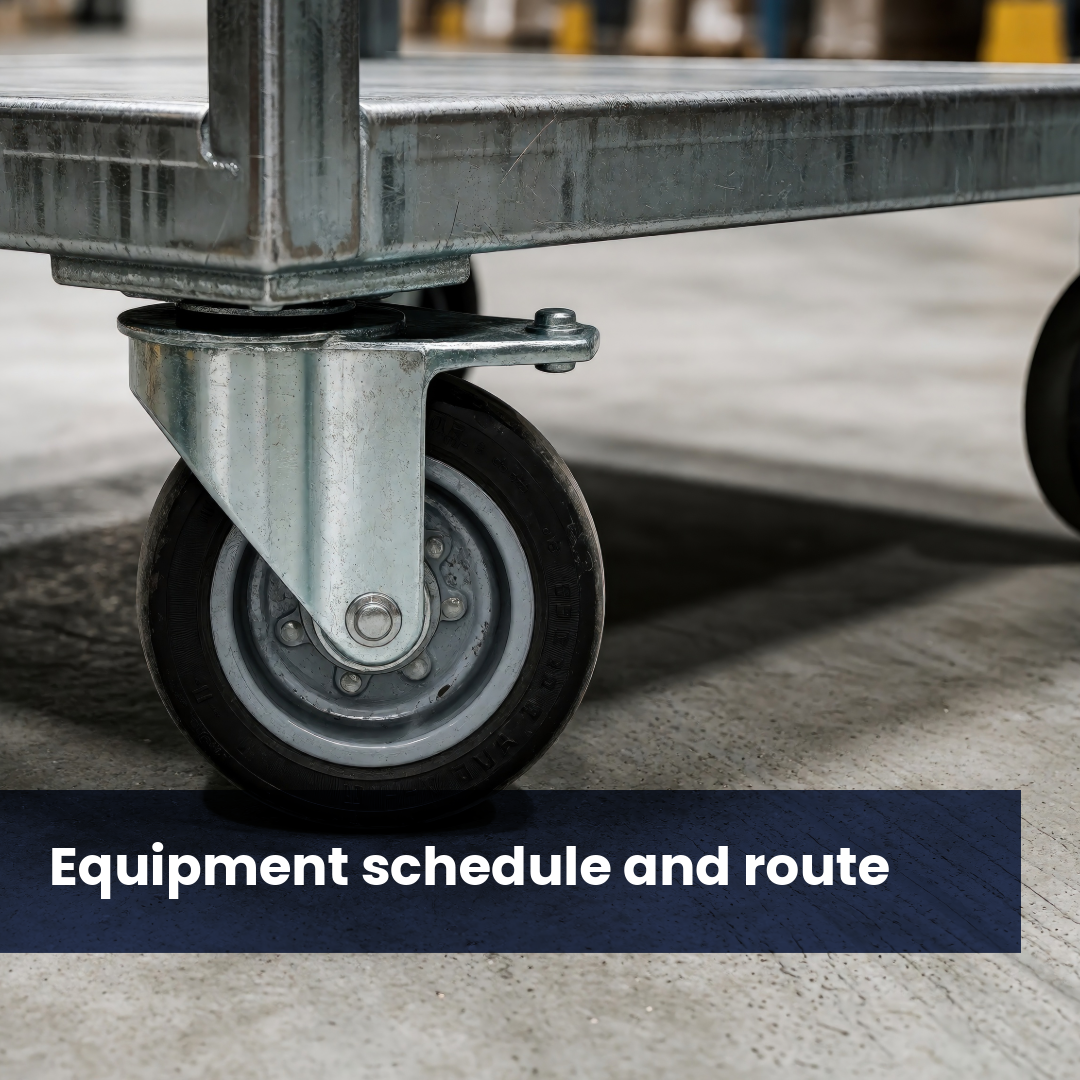
Rolling loads: loaded cabinets, lifts or other equipment moving across the floor during installation and maintenance, including the delivery route.
The load path: how the panel, pedestal, stringer or other understructure transfers loads to the structural slab.
Ask the equipment and structural teams for these inputs before selecting a panel class. Cemac’s Tate access floor range includes different ConCore panels and understructure options; the appropriate combination depends on the project’s actual loading and operating conditions.
Coordinate Seismic Design and Underfloor Services Together
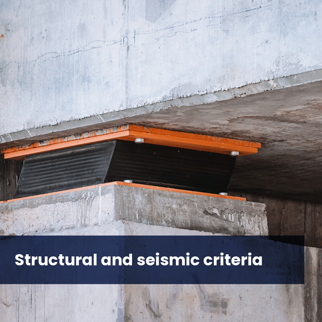
In New Zealand, the project structural engineer should establish the seismic design requirements for the floor assembly and its connection to the slab. Floor height, loading, anchorage, understructure and equipment restraint all need to be considered. A product description alone cannot establish that a proposed installation meets the requirements of a particular building.
For example, Tate’s bolted stringer systems offer lateral resistance to heavy rolling and seismic loading, with seismic force-resistant pedestal options available. The final arrangement still needs project-specific engineering and coordination.
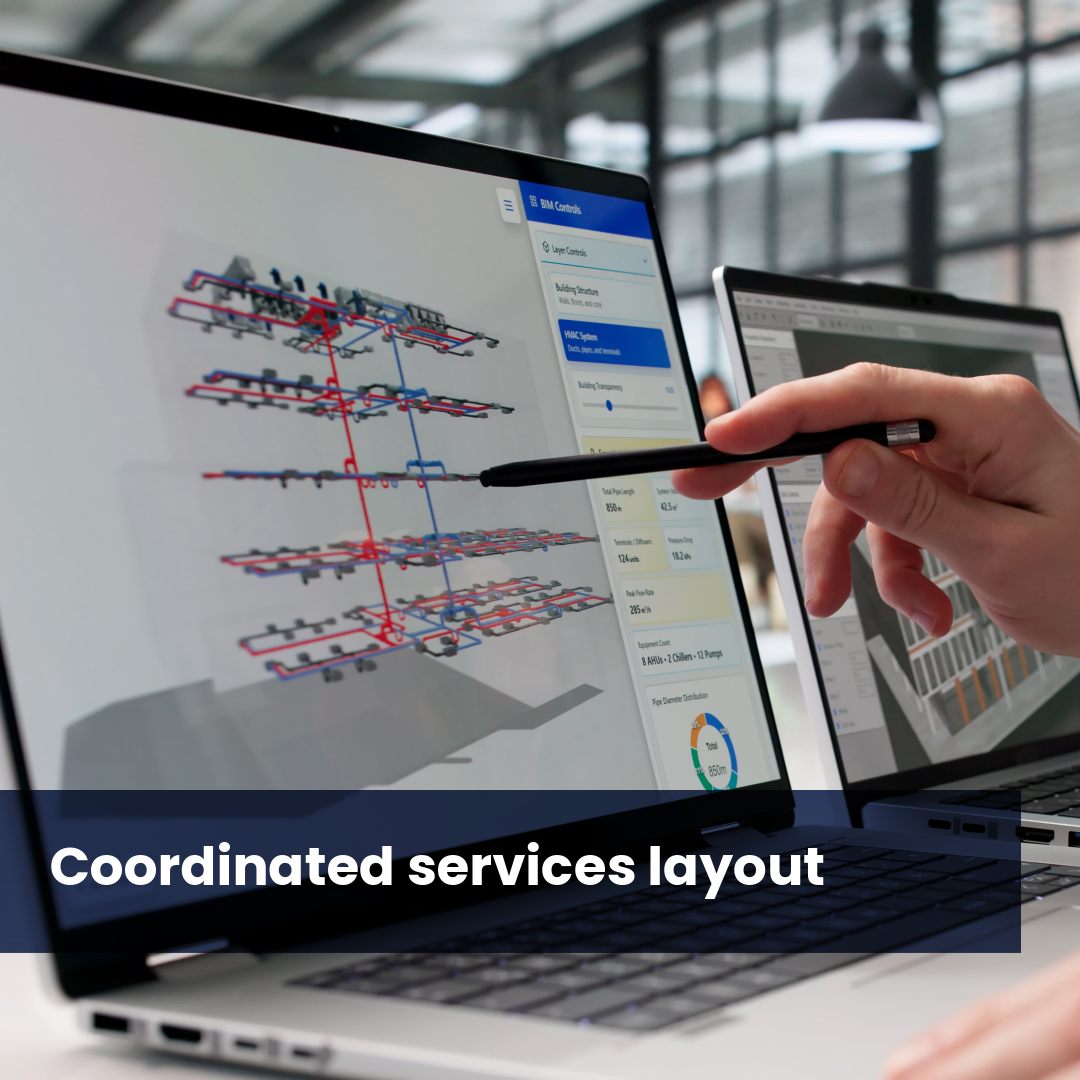
That coordination should happen in three dimensions. Pedestals, stringers and any required restraint can occupy the same space as cable trays, power distribution, pipework and floor penetrations. Modelling the floor grid alongside the services and rack layout makes clashes easier to identify while routes can still be changed. The relevant consultants should also establish responsibility for fire protection, earthing and leak detection where those systems affect the underfloor zone.
“If the void supplies conditioned air, the raised floor is part of the mechanical design.”
Treat an Air Plenum as Part of the Cooling System
If the void supplies conditioned air, the raised floor is part of the mechanical design. Plenum depth, pressure, obstructions, leakage and the location of airflow panels all affect how air reaches equipment. Unsealed cable openings and a service route across the air path can undermine an otherwise well planned layout.
Coordinate airflow panels with rack positions and containment, then detail and commission the openings as part of the whole cooling strategy. Cemac’s airflow panels offer different distribution and control options, but panel selection should follow the mechanical design.
Where liquid cooling is planned, confirm where pipework, manifolds and leak detection will go. Do not assume every cooling service belongs beneath the floor. The choice between underfloor and overhead routes affects access, available space and the other systems sharing the zone.
Resolve the Edges, Openings and Access
The difficult details are often at the boundaries of the floor: columns, walls, partitions, doorways, ramps and changes in level. Show how the panel grid meets these conditions, where equipment feet will land and how technicians will lift panels after racks and partitions are installed.
Coordinate cable and pipe penetrations with the panel supports before openings are cut. Where the void is used for air distribution, specify how penetrations and perimeter joints will be sealed. Finishes, cleaning, slip resistance and any electrostatic requirements should also reflect the equipment and operating brief rather than a standard detail copied from another project.
What to Provide Before the Floor Is Specified
A useful design-stage package gives the access floor specialist enough information to recommend a complete system, not just a panel.
Include:
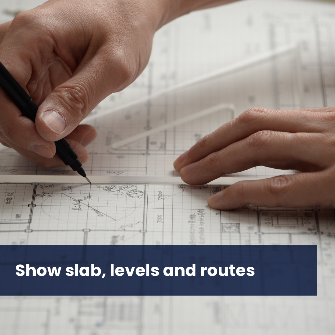

1) Architectural plans and sections showing the slab, finished floor level, adjacent levels, access routes and overhead clearances.
2) An equipment schedule with loaded weights, feet or castors, cabinet positions and the route for moving equipment into place.
3) Structural and seismic design criteria, including responsibility for floor anchorage and equipment restraint.
4) A coordinated services layout showing underfloor routes, access points, risers and proposed penetrations.
5) The mechanical strategy, including whether the void is an air plenum and how it relates to rack layout and containment.
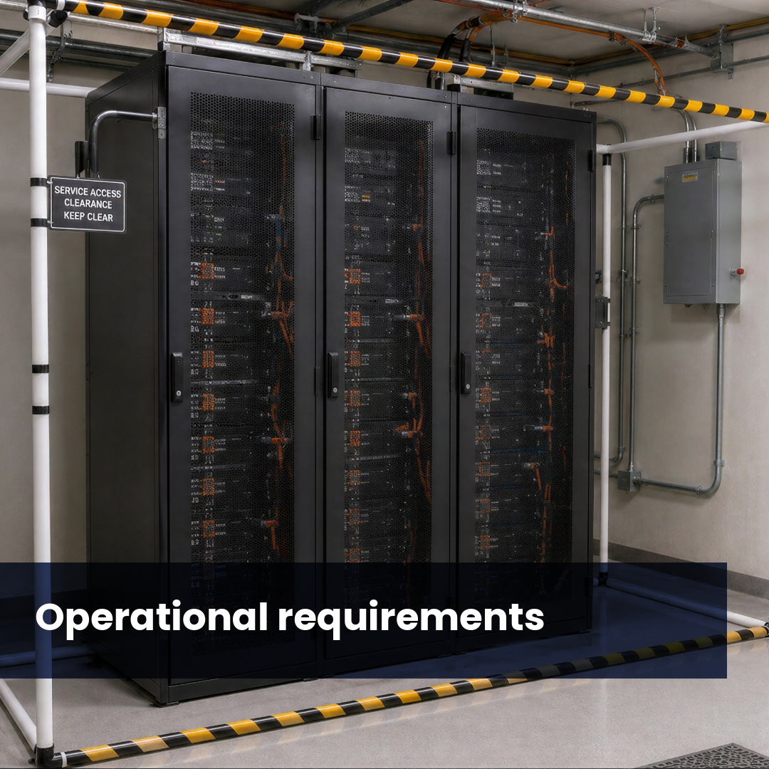
6) Operational requirements for maintenance access, finishes and relevant fire, earthing or leak detection interfaces.
Cemac Data Centre Solutions supplies and installs Tate raised access floor systems and supports projects with BIM modelling, seismic assessment and coordination.